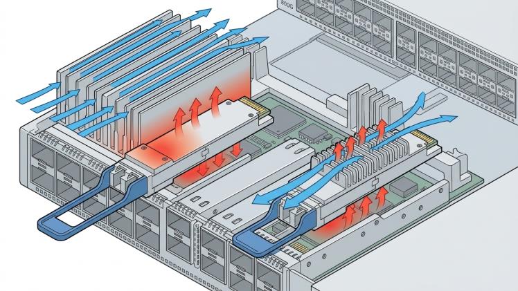

As data center networks move to 800G Ethernet, optical transceiver selection involves more than optical performance and transmission distance. Thermal management becomes increasingly important as switch ports become denser and power consumption rises. For 800G OSFP FR4 deployments, flat-top and finned-top module designs can influence how heat is transferred and managed. Understanding these differences helps network engineers choose modules that match their switch platforms and operating conditions.
Understanding the Two OSFP Designs
A flat-top OSFP has a relatively smooth upper surface, while a finned-top design incorporates raised fins that increase the exposed surface area available for heat transfer. These structural differences affect how the module interacts with the host system’s cooling arrangement.
However, the top shape alone does not determine cooling performance. The module’s internal thermal design, contact with the host heatsink, airflow direction, and overall system configuration all contribute to temperature management. Two modules with different exterior designs may perform differently depending on the platform for which they were designed.
Why Cooling Requirements Matter at 800G
An 800G FR4 transceiver processes high-speed optical signals across multiple wavelengths, and its electronic and optical components generate heat during operation. If the module operates outside its specified temperature range, performance may become unstable or the host system may trigger protective measures.
A finned-top design can provide additional surface area for heat dissipation, but its effectiveness depends on airflow and the surrounding thermal environment. A flat-top module may instead rely on a platform-specific heatsink or cooling interface. Neither design should be assumed to offer better cooling in every deployment.
The correct choice is the configuration validated by the transceiver manufacturer and the switch platform vendor.
Consider Airflow and Port Density
High-density switches introduce additional thermal challenges. Airflow may be restricted by neighboring modules, cable routing, heatsink geometry, and the arrangement of components inside the chassis. In systems with many active 800G ports, these factors can influence the temperature of individual modules and the overall cooling load.
Before deployment, verify the switch’s airflow direction and supported module configuration. Check whether the platform requires a particular OSFP top style, heatsink arrangement, or thermal interface. Avoid assuming that a module will fit and cool correctly simply because its connector and form factor appear compatible.
Cable management also deserves attention. Dense fiber connections should be routed without obstructing airflow or placing unnecessary mechanical stress on the module interface.
Check Platform Compatibility Before Ordering
Flat-top and finned-top OSFP modules are not automatically interchangeable. A switch may be designed and validated for a specific module cooling arrangement, and physical clearance alone does not establish thermal compatibility.
Review the switch hardware documentation and the transceiver datasheet before purchasing. Confirm the supported OSFP configuration, module power requirements, operating temperature range, cooling method, and compatibility with the intended system. Where available, use the manufacturer’s validated compatibility information rather than relying on appearance or general assumptions about heatsink design.
For large deployments, testing a representative configuration under realistic operating conditions can help identify thermal constraints before the full installation.
Choose the Design for the System
Selecting an 800G FR4 transceiver requires a system-level approach. Flat-top and finned-top designs offer different physical approaches to thermal management, but their suitability depends on the host platform, airflow, port density, and manufacturer specifications.
By verifying cooling requirements and platform compatibility before deployment, network teams can reduce integration risks and maintain more predictable operating conditions. The best OSFP design is not necessarily the one with the most visible fins; it is the one validated to operate reliably within the intended switch environment.